From S.H.O.
|
|
| Line 1: |
Line 1: |
| − | {{DISPLAYTITLE:Presentation → Phase 1}} | + | {{DISPLAYTITLE:April 2016 Presentation → Phase 1}} |
| | [[File:Let's Build the S.H.O. Drive! - Slide 018 of 176.png|thumb|<div style="float: right">Slide 018 of 176</div>]] | | [[File:Let's Build the S.H.O. Drive! - Slide 018 of 176.png|thumb|<div style="float: right">Slide 018 of 176</div>]] |
| | '''In Phase 1…'''<br>• First on the list is to create holes which will hold bearings for the S.H.O. Drive.<br>• Second is to install brass hinges which will connect the wood panels to the wood base.<br>• And third is to install square nuts onto the shaft. | | '''In Phase 1…'''<br>• First on the list is to create holes which will hold bearings for the S.H.O. Drive.<br>• Second is to install brass hinges which will connect the wood panels to the wood base.<br>• And third is to install square nuts onto the shaft. |
Latest revision as of 11:12, 28 August 2016
In Phase 1…
• First on the list is to create holes which will hold bearings for the S.H.O. Drive.
• Second is to install brass hinges which will connect the wood panels to the wood base.
• And third is to install square nuts onto the shaft.
Bearing holes
(Top)
| 2 Barn Birdhouse Kits
(Phase 1 Parts)
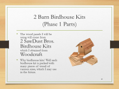
• The wood panels I will be using will come from 2 SawDust Bros. Birdhouse Kits which I obtained from Woodcraft.
• Why birdhouse kits? Well each birdhouse kit is packed with many pieces of wood of various sizes, which I may use in the future. |
| Saving Time
(Protocols)
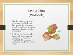
• But the main reason why I purchased two Birdhouse kits was for the two front panels, which have holes that are nearly the right size for the project.
• I will use the front panels from each kit as support structures to carry the weight of the bearings, rotor, and conductive copper coils. |
| Hole Size
(Compatibility)
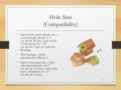
• Each front panel already has a conveniently placed 1½” (or about 38 mm) hole which I will expand by 1/8” (or about 3 mm) to hold the bearings.
• The bearings will be introduced in Phase 2.
• Each front panel has a base side measurement of 6” (or about 150 mm). Also, they have a thickness of ½” (or about 13 mm). |
| Circle Template
(Phase 1 Tools)
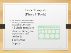
• To mark the dimensions for the 1 5/8 ” (or about 41 mm) bearing holes, I bought a 42 circle template sheet by Timely from a specialty store called Artist & Craftsman Supply. |
| Power Drill
(Phase 1 Tools)
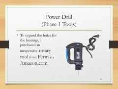
• To expand the holes for the bearings, I purchased an inexpensive rotary tool from Ferm via Amazon.com. |
| Portable Work Bench
(Equipment)
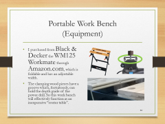
• I purchased from Black & Decker the WM125 Workmate through Amazon.com, which is foldable and has an adjustable width.
• The clamping wood pieces have a groove which, fortuitously, can hold the depth guide of the power drill. So this work bench will effectively function as an inexpensive “router table”. |
| Dremel Accessory Set
(Phase 1 Tools)
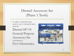
• In order to finish the holes nicely to size, I will attach items from the Dremel 687-01 General Purpose Accessory Set I purchased at Fry’s Electronics. |
| Sanding Bands & Drum
(Phase 1 Tools)
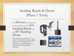
• The Dremel tools from the kit that I will use are the 432 Sanding Bands and the 407 Sanding Drum.
• The sanding area will be ½” (or about 13 mm) thick, which will be perfect for sanding into the ½” (or about 13 mm) thick wood panels which will hold the bearings. |
|
Hinged support "feet"
(Top)
| Plywood Surface
(Equipment)
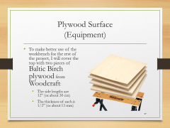
• To make better use of the workbench for the rest of the project, I will cover the top with two pieces of Baltic Birch plywood from Woodcraft:
• The side lengths are 12” (or about 30 cm)
• The thickness of each is 1/2” (or about 13 mm) |
| C-Clamps
(Equipment)
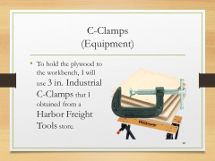
• To hold the plywood to the workbench, I will use 3 in. Industrial C-Clamps that I obtained from a Harbor Freight Tools store. |
| Ash Wood Blocks
(Phase 1 Parts)
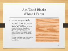
• I also have two separate Ash wood blocks, also from Woodcraft that are about 2 inches by 2 inches thick. That’s about 50 millimeters on each side. Their length is about 8 inches long, or about 200 millimeters. These blocks will serve as the “feet” of the S.H.O. Drive.
• If you’re wondering what Ash wood is used for, it’s a wood often used in baseball bats. |
| Brass Hinges
(Phase 1 Parts)
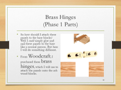
• So how should I attach these panels to the base blocks? Well I could simply glue and nail these panels to the base like a normal person. But here I will do something different.
• From Woodcraft, I purchased these brass hinges, which I will use to attach the panels onto the ash wood blocks. |
| Transparency
(Protocols)
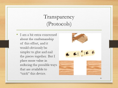
• I am a bit extra-concerned about the craftsmanship of this effort, and it would obviously be simpler to glue and nail the pieces together. But I place more value in reducing the possible ways that are available to “trick” this device. |
| Transparency
(Protocols)
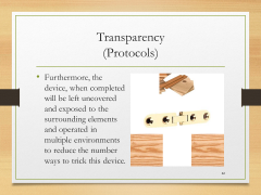
• Furthermore, the device, when completed will be left uncovered and exposed to the surrounding elements and operated in multiple environments to reduce the number ways to trick this device. |
| Transparency
(Protocols)
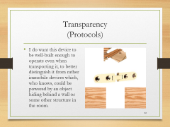
• I do want this device to be well-built enough to operate even when transporting it, to better distinguish it from rather immobile devices which, who knows, could be powered by an object hiding behind a wall or some other structure in the room. |
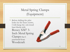
| Metal Spring Clamps
(Equipment)
• Before drilling the pilot holes for the brass screws, I will clamp the Ash wood base blocks with Bessey XM7 3-Inch Metal Spring Clamps that I purchased from Woodcraft. |
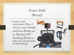
| Power Drill
(Recap)
• Earlier in this construction Phase, I will have used a rotary tool from Ferm and the Dremel 407 Sanding Drum to make neat circular holes for the bearings. |
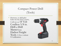
| Compact Power Drill
(Tools)
• However, to drill pilot holes for the brass screws, I will use an 18 Volt Cordless 3/8 in. Drill by Drill Master from Harbor Freight Tools. 3/8 in. is about 9.5 millimeters. |
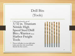
| Drill Bits
(Tools)
• I also purchased a set of 3/32 in. Titanium Nitride High Speed Steel Drill Bits by Warrior from Harbor Freight Tools.
• These will allow to me drill pilot holes into the Ash wood base blocks for the screws. |
| Brass Screws
(Parts)
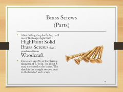
• After drilling the pilot holes, I will screw the hinges tight with HighPoint Solid Brass Screws that I purchased from Woodcraft.
• These are size #6 so they have a diameter of 5/16 in. (or about 8 mm) measured at the shank. The shank is the straight section next to the head of each screw. |
| Screw Driver Set
(Tools)
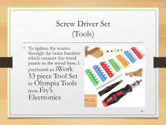
• To tighten the screws through the brass brackets which connect the wood panels to the wood base, I purchased an iWork 53 piece Tool Set by Olympia Tools from Fry’s Electronics. |
|
Preparing the shaft for rotor assembly
(Top)
| Square Nuts and Rod
(Phase 1 Parts)
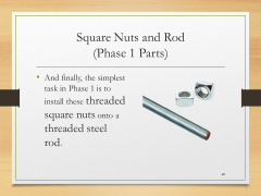
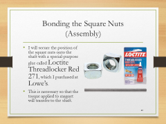
• And finally, the simplest task in Phase 1 is to install these threaded square nuts onto a threaded steel rod. |
| Square Nuts and Rod
(Phase 1 Parts)
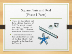
• These are zinc plated and have a fitting diameter of 5/8” (or about 16 mm) and have 11 threads per inch (11 TPI). I obtained these from Tacoma Screw.
• Their diameter matches the size for the bore hole of the fan, which I will describe in further detail in Phase 4. |
| Neo Magnets
(Compatibility)
• These square nuts have a side length of 1” (or 25.4 mm). This is useful because the very strong Neodymium magnets that I will use for this project have imperial measurements whose thickness is ½” (or 12.7 mm). So these magnets will bond straight and level with the square nuts solely through their magnetic attraction, and no glue will be necessary on the magnets themselves. |
| Bonding the Square Nuts
(Assembly)
• I will secure the position of the square nuts onto the shaft with a special-purpose glue called Loctite Threadlocker Red 271, which I purchased at Lowe’s.
• This is necessary so that the torque applied to magnet will transfer to the shaft. |
|
April 2016 Presentation
(Top)
| I
|

Introduction
Summary of measuring devices, back up and safety equipment, and camcorder (+accessories)
|
| 1
|
Phase 1
Holes, brass hinges, square nuts
|
| 2
|
Phase 2
Neodymium magnets and bearings
|
| 3
|
Phase 3
Spool, coils, and ceiling hooks
|
| 4
|
Phase 4
No hidden batteries, increase rigidity, hex nuts, terminal rings, toggle switch, fan blades, and extended test run
|
| 5
|
Phase 5
Heavy duty basket, S.H.O. Drive insertion, secure meters, and portable extended test run
|
| 6
|
Phase 6
Square tote, plastic spools, protective edge trim, and enclosed extended test run
|
| 7
|
Phase 7
Prepare elevated test platform, outdoor test setup, camcorder hookup to portable power, and outdoor extended test run
|
Site map
HQ ● Glossary ● April 2016 Presentation


