Difference between revisions of "S.H.O. Drive Mark I"
(→Distance along shaft length (Depth)) |
(→Presentation Outline (for S.H.O. Drive Alpha)) |
||
| Line 15: | Line 15: | ||
[[Presentation]] | [[Presentation]] | ||
| + | <div style="float: left"> | ||
* [[Presentation/Introduction]] | * [[Presentation/Introduction]] | ||
** [[Presentation/Introduction#Measuring devices|Measuring devices]] | ** [[Presentation/Introduction#Measuring devices|Measuring devices]] | ||
| Line 20: | Line 21: | ||
** [[Presentation/Introduction#Safety gear|Safety gear]] | ** [[Presentation/Introduction#Safety gear|Safety gear]] | ||
** [[Presentation/Introduction#Recording device and accessories|Recording device and accessories]] | ** [[Presentation/Introduction#Recording device and accessories|Recording device and accessories]] | ||
| + | </div> | ||
| + | <div style="float: left"> | ||
* [[Presentation/Phase 1|Phase 1]] | * [[Presentation/Phase 1|Phase 1]] | ||
** [[Presentation/Phase 1#Bearing holes|Bearing holes]] | ** [[Presentation/Phase 1#Bearing holes|Bearing holes]] | ||
** [[Presentation/Phase 1#Hinged support "feet"|Hinged support "feet"]] | ** [[Presentation/Phase 1#Hinged support "feet"|Hinged support "feet"]] | ||
** [[Presentation/Phase 1#Preparing the shaft for rotor assembly|Preparing the shaft for rotor assembly]] | ** [[Presentation/Phase 1#Preparing the shaft for rotor assembly|Preparing the shaft for rotor assembly]] | ||
| + | </div> | ||
| + | <div style="float: left"> | ||
* [[Presentation/Phase 2|Phase 2]] | * [[Presentation/Phase 2|Phase 2]] | ||
** [[Presentation/Phase 2#Neodymium magnets|Neodymium magnets]] | ** [[Presentation/Phase 2#Neodymium magnets|Neodymium magnets]] | ||
** [[Presentation/Phase 2#Assembling the magnet rotor stack|Assembling the magnet rotor stack]] | ** [[Presentation/Phase 2#Assembling the magnet rotor stack|Assembling the magnet rotor stack]] | ||
** [[Presentation/Phase 2#Inserting the rotor|Inserting the rotor]] | ** [[Presentation/Phase 2#Inserting the rotor|Inserting the rotor]] | ||
| + | </div> | ||
| + | <div style="float: left"> | ||
* [[Presentation/Phase 3|Phase 3]] | * [[Presentation/Phase 3|Phase 3]] | ||
** [[Presentation/Phase 3#Magnet wires|Magnet wires]] | ** [[Presentation/Phase 3#Magnet wires|Magnet wires]] | ||
| Line 34: | Line 41: | ||
** [[Presentation/Phase 3#Ceiling hooks|Ceiling hooks]] | ** [[Presentation/Phase 3#Ceiling hooks|Ceiling hooks]] | ||
** [[Presentation/Phase 3#Connecting the S.H.O. Coils|Connecting the S.H.O. Coils]] | ** [[Presentation/Phase 3#Connecting the S.H.O. Coils|Connecting the S.H.O. Coils]] | ||
| + | </div> | ||
| + | <div style="float: left"> | ||
* [[Presentation/Phase 4|Phase 4]] | * [[Presentation/Phase 4|Phase 4]] | ||
** [[Presentation/Phase 4#No hidden batteries|No hidden batteries]] | ** [[Presentation/Phase 4#No hidden batteries|No hidden batteries]] | ||
| Line 44: | Line 53: | ||
** [[Presentation/Phase 4#Load assembly|Load assembly]] | ** [[Presentation/Phase 4#Load assembly|Load assembly]] | ||
** [[Presentation/Phase 4#Testing setup and procedure|Testing setup and procedure]] | ** [[Presentation/Phase 4#Testing setup and procedure|Testing setup and procedure]] | ||
| + | </div> | ||
| + | <div style="float: left"> | ||
* [[Presentation/Phase 5|Phase 5]] | * [[Presentation/Phase 5|Phase 5]] | ||
** [[Presentation/Phase 5#Carrying crate|Carrying crate]] | ** [[Presentation/Phase 5#Carrying crate|Carrying crate]] | ||
| Line 49: | Line 60: | ||
** [[Presentation/Phase 5#Securing the meters|Securing the meters]] | ** [[Presentation/Phase 5#Securing the meters|Securing the meters]] | ||
** [[Presentation/Phase 5#Portable test|Portable test]] | ** [[Presentation/Phase 5#Portable test|Portable test]] | ||
| + | </div> | ||
| + | <div style="float: left"> | ||
* [[Presentation/Phase 6|Phase 6]] | * [[Presentation/Phase 6|Phase 6]] | ||
** [[Presentation/Phase 6#Inserting the S.H.O. Drive|Inserting the S.H.O. Drive]] | ** [[Presentation/Phase 6#Inserting the S.H.O. Drive|Inserting the S.H.O. Drive]] | ||
** [[Presentation/Phase 6#Enclosure test|Enclosure test]] | ** [[Presentation/Phase 6#Enclosure test|Enclosure test]] | ||
| + | </div> | ||
| + | <div style="float: left"> | ||
* [[Presentation/Phase 7|Phase 7]] | * [[Presentation/Phase 7|Phase 7]] | ||
** [[Presentation/Phase 7#Standing structure|Standing structure]] | ** [[Presentation/Phase 7#Standing structure|Standing structure]] | ||
| Line 58: | Line 73: | ||
** [[Presentation/Phase 7#Recording setup|Recording setup]] | ** [[Presentation/Phase 7#Recording setup|Recording setup]] | ||
** [[Presentation/Phase 7#Outdoor test|Outdoor test]] | ** [[Presentation/Phase 7#Outdoor test|Outdoor test]] | ||
| + | </div> | ||
==Build Gallery== | ==Build Gallery== | ||
Revision as of 11:33, 28 August 2016
S.H.O. Drive Mark I will be the world's first S.H.O. drive. Come back in the next couple months for major updates! S.H.O. talk 21:35, 5 May 2016 (PDT)
S.H.O. Drive Mark Alpha refers to the original plan for world's first S.H.O. Drive. The actual build will incorporate clear acrylic tubes to elevate the wooden panels inside the crate for maximum transparency and minimization of the ways to hide batteries. A build and demonstration was planned for the 4th of July, but I decided that more planning was need in terms of the logistics of the demonstration as well as the final shape of the S.H.O. Coils. The build time to make the S.H.O. Drive is, and I estimate, to be around 5 hours. Since the video showing the build must be done in one take, I have to make sure that I have my ideas lined up, so this way they come out smoothly in the presentation. Also, cost information is not listed for S.H.O. Drive Alpha because it is preliminary work, but when the world's first S.H.O. drive is built, the cost information for that build will be made available. Sincerely, S.H.O. talk 20:06, 4 July 2016 (PDT)
Contents
Presentation Outline (for S.H.O. Drive Alpha)
Build Gallery
August 14, 2016
|

.JPG)
.JPG)

.JPG)
.JPG)
.JPG)
.JPG)

.JPG)
.JPG)
.JPG)
.JPG)

.JPG)
.JPG)
Dimensions
Distance along shaft length (Depth)
 For design plan as of August 14, 2016

 inches
 1 7/8 back end assembly behind panel
 5/8   square acrylic support rod
 1/4   square acrylic support rod
 1/2   acrylic panel
 7/8   vinyl cup hooks
 3/8   air gap
 1 1/2 neo magnets
 3/8   air gap
 7/8   vinyl cup hooks
 1/2   acrylic panel
 1/4   square acrylic support rod
 5/8   square acrylic support rod
 3 3/8 front end assembly in front of panel

 12    total length of shaft
 For design plan as of August 28, 2016

 inches
 1 7/8 back end assembly behind panel
 5/8   square acrylic support rod
 1/2   acrylic panel
 1 1/4 vinyl cup hooks
 1/4   air gap
 1 1/2 neo magnets
 1/4   air gap
 1 1/4 vinyl cup hooks
 1/2   acrylic panel
 5/8   square acrylic support rod
 3 3/8 front end assembly in front of panel

 12    total length of shaft

 Reason for change: The wound coils have a larger thickness to due an intentionally-reduced perimeter of the actual winding vs. the original plan.
April 2016 Presentation
| I |  Introduction Summary of measuring devices, back up and safety equipment, and camcorder (+accessories) |
|---|
| 1 |  Phase 1 Holes, brass hinges, square nuts |
|---|
| 2 | 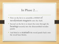 Phase 2 Neodymium magnets and bearings |
|---|
| 3 | 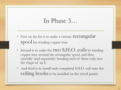 Phase 3 Spool, coils, and ceiling hooks |
|---|
| 4 | 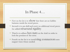 Phase 4 No hidden batteries, increase rigidity, hex nuts, terminal rings, toggle switch, fan blades, and extended test run |
|---|
| 5 | 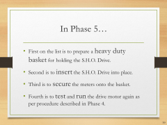 Phase 5 Heavy duty basket, S.H.O. Drive insertion, secure meters, and portable extended test run |
|---|
| 6 | 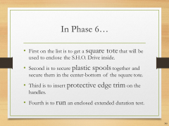 Phase 6 Square tote, plastic spools, protective edge trim, and enclosed extended test run |
|---|
| 7 | 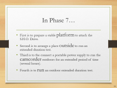 Phase 7 Prepare elevated test platform, outdoor test setup, camcorder hookup to portable power, and outdoor extended test run |
|---|
Site map
HQ ● Glossary ● April 2016 Presentation
|
|